
Keywords: MCLIB, Monte Carlo, Simulation, Neutron Instruments
The Neutron Instrument Simulation Package (NISP) consists of three parts. At the lowest level is the library of functions, MCLIB, including routines for transport and vector analysis, materials properties, scattering kernels, various random distributions, and general utilities. The program that runs simulations using the library functions is MC_RUN. Because the preparation of the geometry file describing an instrument can be "painful" for all but the most experienced users, a web interface, MC_Web, is being developed. This web application is described in these proceedings in the paper by Thelliez et al.. We also ask you to visit the site at http://bayberry.lanl.gov/lansce/Welcome.html. User input relating to both structure and content is vital to this project.
The goals of the NISP are:
- Must be easy to use and interactive
- Must be fast enough to make parameter searches possible
- Must be "open," with defined standards for codes
Uses of the NISP extend beyond simple performance analysis. It is far more economical to test new instrument concepts or to design and test optical components before construction. Because of the high cost of intense neutron sources, it is essential to optimize instrument performance and to verify design specifications. In addition, such Monte Carlo simulations can be used to assist the analysis of complex experimental results. Finally, the NISP may prove a valuable pedagogical tool, in teaching neutron scattering techniques.
2. Program MC_RUN
A flow chart of the execution program MC_RUN is given in Fig. 1
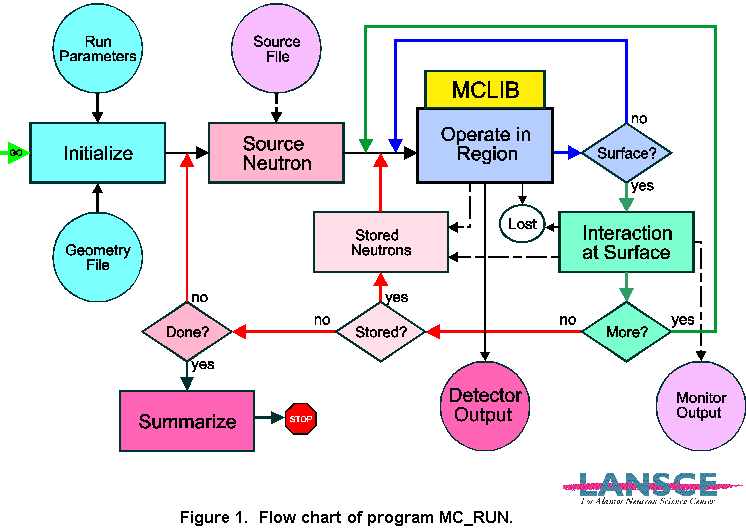
There are three nested loops: the outermost loop is over the number
of source neutrons (with a branch for stored and repeated neutrons); the
next is transport between regions, determination of the subsequent region,
and the interaction at the surface; and the innermost loop is what happens
within any given region (subroutine OPERATE). All geometric relations
between regions are handled in this main code, and all physics and algorithms
of elements within regions are accessed through OPERATE, either
as in-line code or as external procedures. The operation loop continues
until the neutron reaches an exit surface of the region (or vanishes).
Possible outputs of the operation include storing a created neutron for
subsequent tracking, detection of the neutron, or absorption. It is within
this loop that the MCLIB library is applied, and it is here that new features
and modules may be inserted. A more complete description of the philosophy
and structure of MCLIB (and MC_RUN) is to be found in the report "The MCLIB
Library: Monte Carlo Simulation of Neutron Scattering Instruments," which
may be accessed by anonymous ftp from ftp://azoth.lansce.lanl.gov/pub/mclib/document
(hereafter referenced as the "MCLIB Document"). Note that the MCLIB Document
is available in various file formats, and is updated frequently as features
are added.
3. Structures used in MCLIB / MC_RUN
The source codes for the Monte Carlo Library MCLIB and MC_RUN are written in a subset of ANSI-standard Fortran 90 (F90). To improve portability, only F90 features that are also included as "VAX extensions" to F77 are used (F77/VAX). Declaration statements use the F77 format, which is allowed in F90. Two exceptions to the F90 standard are that the character "." is used as the structure delimiter instead of "%", and that structures are defined and declared in STRUCTURE and RECORD statements instead of TYPE; these are again to improve portability to F77/VAX compilers. We have only found one F90 compiler (Lahey) which will not accept these forms. F90 is a structured language, but not object oriented. Some concepts of object-oriented programming are used, but the emphasis is placed on execution speed. The fundamental structures are PARTICLE, SURFACE, REGION, and MC_ELEMENT. These are illustrated in Fig. 2, and defined completely in file MC_GEOM.INC.
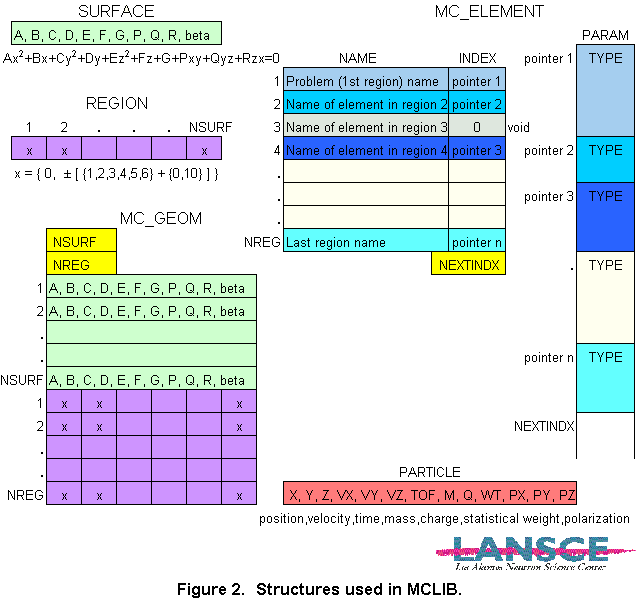
The elements of a PARTICLE structure are
A module may use and change any of the components of a particle sent to it. For instance, motion is accomplished by updating X, Y, Z, and TOF, or partial absorption by decreasing WT. A particle may be split by making a copy and apportioning the original WT between the two instances. Examples of these operations are given below.
The elements of a SURFACE structure are the ten coefficients of a general quadratic surface and a parameter describing the surface roughness. The equation of a surface is
A x2 + B x + C y2 + D y + E z2 + F z + G + P xy + Q yz + R zx = 0
The surface roughness parameter BETA is presently defined only for values between 0 and +1 as a long-range waviness. It is the maximum slope error in a cosine distribution, with rms = 0.58 BETA for small values of BETA. We are exploring representation of surface irregularities on shorter length scales, which could be represented by using the sign of BETA as a flag, or by using values > 1. A module may use any predefined surfaces, and may create a surface for its internal use, but must not modify any existing surfaces. Any surface more complex than quadratic (e.g., a toroid) can only be defined within a module.
A REGION structure is a vector IGEOM of signed integers (INTEGER*2) which give the relationship of the region to every surface. If IGEOM(JSURF) = 0, the region is not bounded by surface JSURF. If not zero, then the sign of the integer defines which side of the surface is "inside" the region by the sign of the above expression when evaluated at a point (x, y, z). That is, in order for a particle to be inside the region, the expression must have the same sign as IGEOM for the surface. (If the expression evaluates to 0, then 1st and 2nd derivatives will also be considered.) The numeric value of IGEOM is also significant:
- ordinary surface described by roughness BETA, with possibility of refraction or critical reflection depending on wavelength and relative index of refraction
- totally reflecting surface (from inside the region)
- diffuse surface (not presently implemented)
- totally absorbing surface when hit from inside the region; i.e., no exit
- special conditions apply before exiting region; for instance, a coordinate transform may be required. Then treat as type 1. An example of this usage is given below.
- treat as type 1, but split the particle into 2 equal instances after crossing
The structure MC_ELEMENT is most relevant when writing a module,
because this is the structure used to define the contents of all regions.
There is a one-to-one correspondence of elements and regions. An element
has a 40-character NAME and an integer pointer INDEX
into an array of REAL*4 parameters, PARAM. (A special
case is void regions, which have INDEX = 0.) The number in the
PARAM block at the location INDEX is the ELMNT_TYPE
of the region; the integer part of the value is the type and fractions
may be used for subtypes. Any number of parameters may be defined; for
each defined type nn, there is also a parameter NUMBER_nn that
is one more than the number of parameters defined. The author of a module
must obtain or assign a type number (70 through 79 are available for ad
hoc or development use), and must define variables with global names.
(Global names are necessary so that the creator of the geometry file will
have exactly the same definitions as the executing program!) Descriptive
names are preferred, and a prefix may be used to identify the relevant
module; documentation of the meanings of the variables is essential. The
names are defined in PARAMETER statements as integer offsets in
the PARAM block, counting from 0 at the location referenced by
INDEX (see examples in MC_ELMNT.INC,
which is a complete list of defined types). A module may modify an entry
in the PARAM block for its own later use, but not as a
mechanism for returning a value to MC_RUN. Use of static local
variables (SAVE statements) is preferred over modifying PARAM
entries. The NAME variable may be used to pass a file name to
the module. The communication between MC_RUN and the modules is described
in the next section. Note that there are rough "classes" of modules, organized
by decades of the type number. In particular, samples are in the range
30-39 and detectors in the range 40-49.
Such classes may share common variable names.
4. Subroutine OPERATE
This subroutine contains the "methods" for every type of element, either in-line or as external subroutine calls. The task of an author of a new module is to incorporate the new type into OPERATE by including a new case. For examples and to show the case structure, excerpts from the subroutine are listed in Appendix C. All of the routines in the MCLIB library as listed and described in the MCLIB Document are available to use in support of new modules. The calling sequence of OPERATE contains arguments to support a variety of classes of elements; for instance, detectors need to return encoding information. The arguments in the calling sequence are listed in Fig. 3.
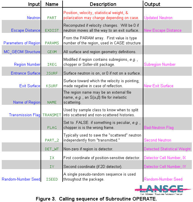
The first argument, PART, is the neutron being tracked. The set of values from the PARAM block that is specific to this element is passed as a vector PARAMS. Within subroutine OPERATE the vector PARAMS is indexed starting at 0, so that the element type is PARAMS(0) and values may be referenced in the form PARAMS(ParameterName), e.g., to calculate macroscopic cross section from a constant and a 1/v term,
NSIG = PARAMS(NSIGMA0) + PARAMS(NSIGMAV)/SQRT(PART.VX**2+PART.VY**2+PART.VZ**2)
When OPERATE is called, MC_RUN has already determined the distance
EXDIST to escape from the region along the initial trajectory
(including gravity), and this is passed as the second argument (useful
for determining attenuation). If the velocity vector (magnitude or direction)
changes within the module, EXDIST must be recomputed by a call
to DTOEX. This allows OPERATE to loop internally (instead
of returning to MC_RUN at each step) for effects such as multiple scattering,
but it means that the entire geometry structure (GEOM) and the
region and surface numbers (IREG, JSURF, and KSURF)
must also be passed as arguments. Other arguments in the calling sequence
support specific classes of elements.
5. Examples of Sample Types
There are "no" restrictions on what may happen to a neutron within a region. As shown in Fig. 1, there are several possible outcomes in addition to the original neutron. A new instance may be created and stored (in MC_RUN) for further tracking; some portion of the neutron may be detected, so detector cell information is returned to MC_RUN for histogramming; some fraction of the neutron may be absorbed ("lost"). Some examples are shown in Figs. 4 and 5.
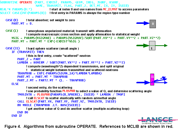
Figure 4 shows how subroutine OPERATE treats region types 0, 1, and 31. (Note: type 31 has subsequently been changed to subtype 1 of type 30.) The simplest operation is total absorption, type 0. Type 1 transmits with attenuation, by modifying PART.WT and then falling through to let the particle be moved to the exit surface. Type 31 (or 30.1) shows how a neutron is split into transmitted and scattered fractions. On the first entry (TRANSMIT = .TRUE.), a second neutron is created as PART2 with the statistical weight partitioned according to the total scattering probability. The first particle is transmitted with attenuation. When called with TRANSMIT=.FALSE., the particle is scattered one or more times according to an algorithm in a probability distribution subroutine.
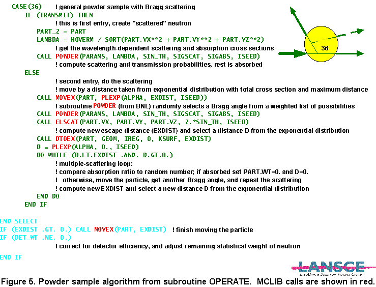
The case shown in Fig. 5, Bragg scattering from a powder, is similar
in the way it creates the scattered neutron, but in this case the multiple
scattering is more sophisticated. The neutron that is going to scatter
is first moved some distance into the sample. The actual shape of the region
is used to determine whether the scattered neutron will escape without
another scattering event. Note that the subroutine used to select a Bragg
scattering angle was developed at Brookhaven national Laboratory and adapted
for use in MCLIB.
6. Conclusion
This report has attempted to describe the current status of the structure
of the MCLIB library, and may be considered as a suggested standard for
the interface between an executing code (such as MC_RUN) and the elements
that actually operate on neutrons. Many features are arbitrary accidents
of history, and it must be expected that improvements will be made both
from the point of view of computer science and also run-time efficiency
(which we take to be the ultimate test).
An international committee has been formed (with Kent Crawford of ANL
as chair) to review this and other codes and to establish standards for
a Neutron Instrument Simulation Package. Please address any questions and
suggestions to PASeeger@aol.com.
This report has not described the process of defining geometry. We invite
you to visit MC_Web
for further information.
This work is supported by the U. S. Department of Energy Office of Basic Energy Sciences and other Department of Energy programs under Contract W-7405-ENG-32 to the University of California.